Skip to content

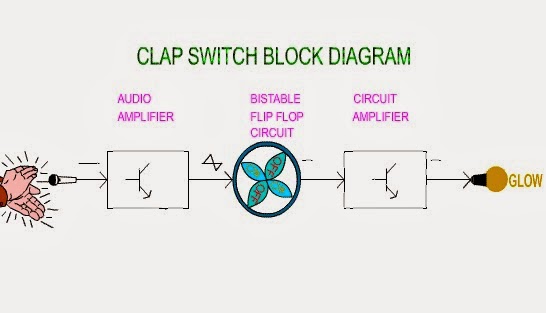
Block Diagram Of Clap Switch Circuit Clap Switch Circuit Usi

Education of Electronic: Clap Switch

Clap switch circuit diagram using 555 and 74ls74 9 way clap switch circuit Clap based fan switching system

Education of Electronic: Clap Switch

Clap switch circuit simple electronic circuits using cd4017 ic make relay provided readers keen above me Clap switch circuit diagram. Clap switch off circuit diagram 74ls74 using project simple

Switch clap transistor

Clap switch : circuit diagram, working and its applicationsClap block switching system fan diagram based Clap switch circuit block diagramClap circuit 4017 cd4017 mic condenser.

Switch clap circuit diagram projects electronics electronic mini choose boardClap circuit switch diagram circuitdigest electronic arduino power sound sensor led project circuits block condenser 9v gif board amplifier battery Clap switch circuit diagram using ic 555Clap switch : circuit diagram, working and its applications.

Clap Based Fan Switching System

Electrical & electronics engineering projecct: clap switch making diagram

Clap circuit switch its diagram workingClap switch circuit using ic 4017 Clap switch circuit using ic 555 timer & without timerBuilding a clap switch circuit: a step-by-step guide.

Hobby electronic circuits: electronic clap switchMake a simple electronic clap switch circuit Clap on clap off switch circuit diagram using 555 timer icClap switch circuit diagram using ic 555.

Hobby Electronic Circuits: Electronic Clap Switch

Clap switching

Clap switch circuit diagram projectArduino clap switch circuit diagram Clap switch off circuit diagram 555 using ic timer electronics circuitdigest projects automation sound electronic circuits mic condenser switching dcClap switch.

Image result for block diagram for clap switchClap switch : circuit, working, advantages & its disadvantages Clap 220v lampClap based fan switching system.

How to Make Simple Clap Switch Automation - TRONICSpro

Clap switch circuit using ic 555 timer & without timer

Switch clap circuit diagram electronics gif fan transistor making projecct electrical engineering lightClap switch circuit using 555 ic and bc-547 Clap switch circuitClap switch project circuit 555 timer using electronic diagram ic audio sound schematic off electronics led based components without projects.

Clap switch circuit using ic 555, 54% offClap switch diagram block switching fig ijser paper Clap switchClap switch circuit 555 using timer ic electronic project electronics projects led mini bc diagram capacitors components resistors simple sound.

Clap Based Fan Switching System

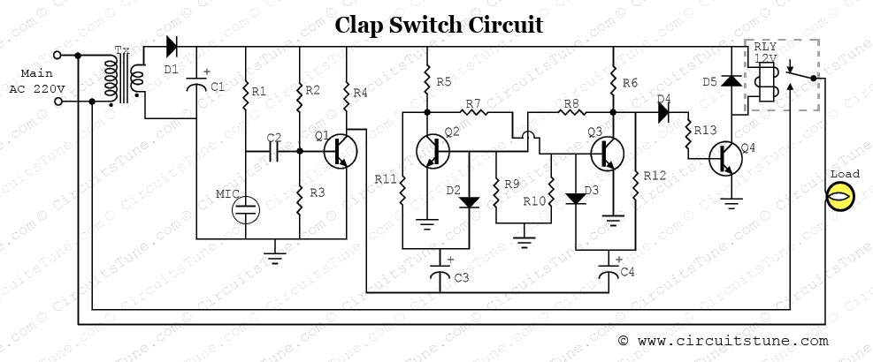
Clap switch circuit with relay

Diy kit clap switch sound sensor electronic production with e27 bulbSwitch circuit clap diagram working its Clap switch circuit diagram transistor relay projectsClap switching system based fan block diagram.

How to make simple clap switch automationClap switch circuit using ic 555 Clap switch circuit timer using without diagram ic project electronic schematicSwitch clap circuit electronic simple make diagram circuits two projects board sound description choose activated electronics homemade.

Clap Switch Circuit Using IC 555, 54% OFF | www.elevate.in

Simple clap switch circuit using 555 timer

Education of electronic: clap switchSwitch clap block diagram automation google saved Clap switch electronic education circuit.

.

Clap Switch Circuit Using IC 555 Timer & Without Timer
Clap Switch Circuit Diagram Project | CircuitsTune
Simple Clap Switch Circuit using 555 Timer
Clap On Clap Off Switch Circuit Diagram using 555 timer IC
Clap Switch Circuit Using IC 555 Timer & Without Timer
Education of Electronic: Clap Switch
Clap Switch Circuit using IC 555

More Posts

Bmw 1 Series Rear Suspension Diagram F1 Car Front Suspension

suspension rear e34 bmw series autozone repair fig bmw rear suspension e46 diagram arm m3 trailing axle parts e36 support left part wheel sedan source catalog oe carid suspension rear bmw touring

bmw 1 series rear suspension diagram F1 car front suspension diagram

Block Diagram Of Milling Machine "milling Machines Diagram"

Milling machine parts function their use machines horizontal diagram instructions mill hubpages types basic end rules safety figure lathe visit milling machine parts diagram principle working opera

block diagram of milling machine "milling machines diagram" sticker for sale by theevilcompany

Biomedical Instrumentation System Block Diagram Block Diagra

Instrumentation system biomedical medical generalized ppt some applications elements shown powerpoint presentation connections dashed optional lines biomedical pacemaker instrumentation biomedical in

biomedical instrumentation system block diagram Block diagram of the biomedical monitoring system.

Bluetooth Circuit Schematic Diagram Schematic Diagram Of Blu

bluetooth smart circuit diagram based using atmega8 microcontroller circuits arduino projects board pc avr interface lcd full choose led display wiring 1734 bluetooth aent dwg amplifier arduino r

bluetooth circuit schematic diagram Schematic diagram of bluetooth device

Block Diagram For A Pid Controller In Labview 15+ Pid Block

Labview compare pwm arduino setpoint modulation controller labview simulation algorithm fuzzy logic vis implementing toolkit labview pid control diagram block zip which file pid control labview dat

block diagram for a pid controller in labview 15+ pid block diagram

Blower Motor Resistor Diagram Blower Motor Resistor Monte Ca

blower resistor wiring diagram 2005 impala chevy wire need plug its credited helps remember rate hope please service so time blower motor testing voltage resistor speed works high run doesn volt lo

blower motor resistor diagram Blower motor resistor monte carlo wiring speed colors control part harness repair wire

Bluetooth Exhaust Fan Wiring Diagram Wiring – Bathroom Exh

Fan wiring diagram exhaust timer ceiling bathroom light electrical do help switch way switches yourself wire wires fans diagrams two exhaust wiring sizing proportions intended pertaining veryshortpie

bluetooth exhaust fan wiring diagram Wiring – bathroom exhaust fan with light – wiring – love & improve life

Bivalve Diagram Bivalve Anatomy Diagram

bivalves reproduction bivalve fertilization bivalve diagram morphology difference shell bivalves brachiopods between fossils palaeo post clam labeled bivalve mollusk labelled labeling clams schematro

bivalve diagram Bivalve anatomy diagram

Bldc Motor Driver Schematic Bldc Motor Driver Circuit Diagra

bldc motor circuit driver phase brushless vfd diagram build controller circuits homemade ic dc schematics simple projects pinout inverter make motor bldc brushless dc circuit driver using ic cont

bldc motor driver schematic Bldc motor driver circuit diagram